Sunday, May 29, 2011

Lab 144 - PIM Sparse-Mode

Prerequisites: CCNP level skills.

Note!
All routers are running EIGRP protocol as well as multicast routing.

Topology

Pic. 1 - Topology Diagram.
Icons designed by: Andrzej Szoblik - http://www.newo.pl

Task 1
Multicast server is located on 10.1.234.0/24 subnet. It sends the multicast stream using 224.4.4.4 address. Enable multicast on all routers so that. R1 should be the Rendezvous Point (RP) in this network.

Solution

Task 1
Multicast server is located on 10.1.234.0/24 subnet. It sends the multicast stream using 224.4.4.4 address. Enable multicast on all routers so that R1 should be the Rendezvous Point (RP) in this network.

All routers:
!
ip pim rp-address 172.16.101.1
!

All routers similar to R1 below (all interfaces are sparse-mode)!

R1 Configuration:
!
interface Ethernet0/0
 ip address 10.1.51.1 255.255.255.0
 ip pim sparse-mode
!
interface Serial1/0
 ip address 10.1.123.1 255.255.255.0
 ip pim sparse-mode
 encapsulation frame-relay
 no ip split-horizon eigrp 100
 serial restart-delay 0
 frame-relay map ip 10.1.123.3 103 broadcast
 frame-relay map ip 10.1.123.2 102 broadcast
 no frame-relay inverse-arp
!
interface Serial1/1
 ip address 10.1.15.1 255.255.255.0
 ip pim sparse-mode
 serial restart-delay 0
!

Verification (here just R1, but done on all routers):

Pic. 2 - R1's Multicast-enabled Interfaces.

Pic. 3 - R's Multicast Neighbors.

All routers know which router is the RP.

Pic. 3 - Routers Recognize RP (here: just R4).

In order to simulate the client on R6 'ip igmp join-group' command is used.

R6 Configuration:
!
interface Ethernet0/0
 ip address 10.1.56.6 255.255.255.0
 ip pim sparse-mode
 ip igmp join-group 224.4.4.4
!

R6 should register the group with RP (172.16.101.1). R5 receives the join 244.4.4.4 message and registers (*,G) entry (multicast) client. Then, DR registers this with R1 (RP).

Pic. 5 - R5's Multicast Routing Table Entry for 224.4.4.4.

Pic. 6 - RP Registers 224.4.4.4 Client.

R4 is sending the traffic towards 224.4.4.4.

Pic. 7 - Ping Test.

Lab 143 - PIM Dense-Mode

Prerequisites: CCNP level skills.

Topology

Pic. 1 - Topology Diagram.
Icons designed by: Andrzej Szoblik - http://www.newo.pl

Task 1
Enable EIGRP AS 100 on all routers to provide reachability between all subnets including loopbacks (172.16.10x.x/24).

Task 2
On 10.1.56.0/24 a video server has been installed. It will send traffic towards 224.5.5.5. Since almost all users will be receiving the stream use the push method to enable multicast support on all routers. Segments which do not wish to receive the video stream should prune the traffic. Verify that the multicast towards 224.5.5.5 works for the clients in 10.1.234.0/24 subnet.

Solution

Task 1
Enable EIGRP AS 100 on all routers to provide reachability between all subnets including loopbacks (172.16.10x.x/24).
R1 Configuration:
!
router eigrp 100
 network 10.1.15.1 0.0.0.0
 network 10.1.51.1 0.0.0.0
 network 10.1.123.1 0.0.0.0
 network 172.16.101.1 0.0.0.0
 no auto-summary
 eigrp router-id 172.16.101.1
!
interface Serial1/0
 ip address 10.1.123.1 255.255.255.0
 ip pim dense-mode
 encapsulation frame-relay
 no ip split-horizon eigrp 100
 serial restart-delay 0
 frame-relay map ip 10.1.123.2 102 broadcast
 frame-relay map ip 10.1.123.3 103 broadcast
 no frame-relay inverse-arp
!

R2 Configuration:
!
router eigrp 100
 network 10.1.123.2 0.0.0.0
 network 10.1.234.2 0.0.0.0
 network 172.16.102.2 0.0.0.0
 no auto-summary
 eigrp router-id 172.16.102.2
!

R3 Configuration:
!
router eigrp 100
 network 10.1.123.3 0.0.0.0
 network 10.1.234.3 0.0.0.0
 network 172.16.103.3 0.0.0.0
 no auto-summary
 eigrp router-id 172.16.103.3
!

R4 Configuration:
!
router eigrp 100
 network 10.1.234.4 0.0.0.0
 network 172.16.104.4 0.0.0.0
 no auto-summary
 eigrp router-id 172.16.104.4
!

R5 Configuration:
!
router eigrp 100
 network 10.1.15.5 0.0.0.0
 network 10.1.51.5 0.0.0.0
 network 10.1.56.5 0.0.0.0
 network 172.16.105.5 0.0.0.0
 no auto-summary
 eigrp router-id 172.16.105.5
!


R6 Configuration:
!
router eigrp 100
 network 10.1.56.6 0.0.0.0
 network 172.16.106.6 0.0.0.0
 no auto-summary
 eigrp router-id 172.16.106.6
!

Task 2
On 10.1.56.0/24 a video server has been installed. It will send traffic towards 224.5.5.5. Since almost all users will be receiving the stream use the push method to enable multicast support on all routers. Segments which do not wish to receive the video stream should prune the traffic. Verify that the multicast towards 224.5.5.5 works for clients in 10.1.234.0/24 subnet.

R1 Configuration:
!
ip multicast-routing 
!
interface Ethernet0/0
 ip address 10.1.51.1 255.255.255.0
 ip pim dense-mode
!
interface Serial1/0
 ip address 10.1.123.1 255.255.255.0
 ip pim dense-mode
 encapsulation frame-relay
 no ip split-horizon eigrp 100
 serial restart-delay 0
 frame-relay map ip 10.1.123.2 102 broadcast
 frame-relay map ip 10.1.123.3 103 broadcast
 no frame-relay inverse-arp
!
interface Serial1/1
 ip address 10.1.15.1 255.255.255.0
 ip pim dense-mode
 serial restart-delay 0
!

R2 Configuration:
!
ip multicast-routing 
!
interface Ethernet0/0
 ip address 10.1.234.2 255.255.255.0
 ip pim dense-mode
!
interface Serial1/0
 ip address 10.1.123.2 255.255.255.0
 ip pim dense-mode
 encapsulation frame-relay
 serial restart-delay 0
 frame-relay map ip 10.1.123.1 201 broadcast
 frame-relay map ip 10.1.123.3 201
 no frame-relay inverse-arp
!

R3 Configuration:
!
ip multicast-routing 
!
interface Ethernet0/0
 ip address 10.1.234.3 255.255.255.0
 ip pim dense-mode
!
interface Serial1/0
 ip address 10.1.123.3 255.255.255.0
 ip pim dense-mode
 encapsulation frame-relay
 serial restart-delay 0
 frame-relay map ip 10.1.123.1 301 broadcast
 frame-relay map ip 10.1.123.2 301
 no frame-relay inverse-arp
!

R4 Configuration:
!
ip multicast-routing 
!
interface Ethernet0/0
 ip address 10.1.234.4 255.255.255.0
 ip pim dense-mode
!

R5 Configuration:
!
ip multicast-routing
!
interface Ethernet0/0
 ip address 10.1.56.5 255.255.255.0
 ip pim dense-mode
!
interface Ethernet0/1
 ip address 10.1.51.5 255.255.255.0
 ip pim dense-mode
!
interface Serial1/0
 ip address 10.1.15.5 255.255.255.0
 ip pim dense-mode
 serial restart-delay 0
!

R6 Configuration:
!
ip multicast-routing
!
interface Ethernet0/0
 ip address 10.1.56.6 255.255.255.0
 ip pim dense-mode
!

Verification:
Pic. 2 - R1's PIM-enabled Interfaces and Neighbors.

Pic. 3 - R2's PIM-enabled Interfaces and Neighbors.

Pic. 4 - R5's PIM-enabled Interfaces and Neighbors.

I also checked 'show ip pim neighbor' on all routers to make sure the PIM neighbor relationship has been established.

In order to verify the multicast, R6 will be my server sending ping packets towards 224.5.5.5. R4 will emulate the client to verify if it receives the traffic.

R4 Configuration:
!
interface Ethernet0/0
 ip address 10.1.234.4 255.255.255.0
 ip pim dense-mode
 ip igmp join-group 224.5.5.5
!

Verification:
Pic. 5 - The multicast routing table on R4.

As expected, the client has been registered since the entry (*,G) shows in the multicast routing table. Ping from R6 towards the group should work now.
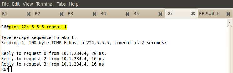
Pic. 6 - Ping Test.

One ping lost due to the path optimization. While continuous pinging from R6 the multicast routing table on R5 below:

Pic. 7 - R5's Multicast Routing Table.

Note!
RPF check is always performed based on the IGP routing protocol (here: EIGRP). STP-bit, chooses the shortest path prunning less optimal EIGRP paths.

Saturday, May 21, 2011

Lab 142 - BGP Timers

Prerequisites: CCNP level skills.

Note!
Configuration from Lab 140.

Topology

Pic. 1 - Topology Diagram.
Icons designed by: Andrzej Szoblik - http://www.newo.pl

Task 1
The BGP policy stipulates that the R5's timer to send BGP advertisements should be set to 10 seconds (default: iBGP=5 seconds, eBGP=30 seconds). Also BGP peer loss should be detected in 15 seconds (default=180 seconds). Also improve the BGP scanner operation by decreasing the default value of 60 seconds to 20 seconds.

Solution

Task 1
The BGP policy stipulates that the R5's timer to send BGP advertisements should be set to 10 seconds (default: iBGP=5 seconds, eBGP=30 seconds). Also BGP peer loss should be detected in 15 seconds (default=180 seconds). Also improve the BGP scanner operation by decreasing the default value of 60 seconds to 20 seconds.

R5 Configuration:
!
router bgp 50
 no synchronization
 bgp router-id 172.16.105.5
 bgp log-neighbor-changes
 bgp scan-time 20
 network 172.16.105.0 mask 255.255.255.0
 timers bgp 5 15
 neighbor 10.1.35.3 remote-as 100
 neighbor 10.1.35.3 advertisement-interval 10
 no auto-summary
!

Note!
Hello timer is set to 5 seconds following the rule 3 x keepalive = holdtime.

BGP Processes:
  • BGP Open - responsible for BGP session establishment.
  • BGP I/O - handles queuing and processing updates and keepalive packets.
  • BGP Scanner - responsible for conditional route advertisements, route dampening, import and export of routes into VRF (MPLS), and confirms the reachability to the NEXT_HOP (the last one is handled now by BGP next-hop tracking).
  • BGP Router - calculates the best path, establishes peers, sends and receives routes and interacts with RIB.
Source:
http://www.cisco.com/en/US/tech/tk365/technologies_tech_note09186a00809d16f0.shtml#understandbgp

Lab 141 - BGP Next-Hop Address Tracking

Prerequisites: CCNP level skills.

Note!
Configuration from Lab 140.

Topology

Pic. 1 - Topology Diagram.
Icons designed by: Andrzej Szoblik - http://www.newo.pl

Task 1
Configure R3 in such a way that the interval between full table walks is 10 seconds (not 5 which is default).

Solution

Task 1
Configure R3 in such a way that the interval between full table walks is 10 seconds (not 5 which is default).


R3 Configuration:
!
R3#show run | s router bgp
router bgp 100
 no synchronization
 bgp router-id 172.16.103.3
 bgp log-neighbor-changes
 bgp nexthop trigger delay 10
 network 172.16.103.0 mask 255.255.255.0
 neighbor 10.1.35.5 remote-as 50
 neighbor 172.16.101.1 remote-as 100
 neighbor 172.16.101.1 update-source Loopback0
 neighbor 172.16.102.2 remote-as 100
 neighbor 172.16.102.2 update-source Loopback0
 neighbor 172.16.104.4 remote-as 100
 neighbor 172.16.104.4 update-source Loopback0
 no auto-summary
!


Note!
The BGP Support for Next-Hop Address Tracking feature is enabled by default when a supporting Cisco IOS software image is installed. BGP next-hop address tracking is event driven. BGP prefixes are automatically tracked as peering sessions are established. Next-hop changes are rapidly reported to the BGP routing process as they are updated in the RIB. This optimization improves overall BGP convergence by reducing the response time to next-hop changes for routes installed in the RIB. When a bestpath calculation is run in between BGP scanner cycles, only next-hop changes are tracked and processed.


Source:
http://www.cisco.com/en/US/docs/ios/12_3t/12_3t14/feature/guide/gt_bnht.html

Thursday, May 19, 2011

Lab 140 - BGP Fast Fallover

Prerequisites: CCNP level skills.

Topology

Pic. 1 - Topology Diagram.
Icons designed by: Andrzej Szoblik - http://www.newo.pl

Task 1
Configure full mesh BGP peering according to the topology diagram (pic. 1). Make sure that all BGP sessions in AS 100 can survive a single link loss. If IGP protocol must used, OSPF should be configured. Advertise Loopbacks into BGP.

Task 2
Configure R3 in such a way so the response time of BGP to adjacency changes is improved. Use a method of detecting the loss of the peer that is not based on the interface state but is event driven such as a loss of the path to the IGP address used for peering.

Solution

Task 1
Configure full mesh BGP peering according to the topology diagram (pic. 1). Make sure that all BGP sessions in AS 100 can survive a single link loss. If IGP protocol must be used, OSPF should be configured. Advertise Loopbacks into BGP.

R1 Configuration:
!
router ospf 1
 router-id 172.16.101.1
 log-adjacency-changes
 network 10.1.13.1 0.0.0.0 area 0
 network 10.1.14.1 0.0.0.0 area 0
 network 172.16.101.1 0.0.0.0 area 0
!
router bgp 100
 no synchronization
 bgp router-id 172.16.101.1
 bgp log-neighbor-changes
 network 172.16.101.0 mask 255.255.255.0
 neighbor 172.16.102.2 remote-as 100
 neighbor 172.16.102.2 update-source Loopback0
 neighbor 172.16.103.3 remote-as 100
 neighbor 172.16.103.3 update-source Loopback0
 neighbor 172.16.104.4 remote-as 100
 neighbor 172.16.104.4 update-source Loopback0
 no auto-summary
!

R2 Configuration:
!
router ospf 1
 router-id 172.16.102.2
 log-adjacency-changes
 network 10.1.23.2 0.0.0.0 area 0
 network 10.1.24.2 0.0.0.0 area 0
 network 172.16.102.2 0.0.0.0 area 0
!
router bgp 100
 no synchronization
 bgp router-id 172.16.102.2
 bgp log-neighbor-changes
 network 172.16.102.0 mask 255.255.255.0
 neighbor 172.16.101.1 remote-as 100
 neighbor 172.16.101.1 update-source Loopback0
 neighbor 172.16.103.3 remote-as 100
 neighbor 172.16.103.3 update-source Loopback0
 neighbor 172.16.104.4 remote-as 100
 neighbor 172.16.104.4 update-source Loopback0
 no auto-summary
!

R3 Configuration:
!
router ospf 1
 router-id 172.16.103.3
 log-adjacency-changes
 network 10.1.13.3 0.0.0.0 area 0
 network 10.1.23.3 0.0.0.0 area 0
 network 172.16.103.3 0.0.0.0 area 0
router bgp 100
 no synchronization
 bgp router-id 172.16.103.3
 bgp log-neighbor-changes
 network 172.16.103.0 mask 255.255.255.0
 neighbor 10.1.35.5 remote-as 50
 neighbor 172.16.101.1 remote-as 100
 neighbor 172.16.101.1 update-source Loopback0
 neighbor 172.16.102.2 remote-as 100
 neighbor 172.16.102.2 update-source Loopback0
 neighbor 172.16.104.4 remote-as 100
 neighbor 172.16.104.4 update-source Loopback0
 no auto-summary
!

R4 Configuration:
!
router ospf 1
 router-id 172.16.104.4
 log-adjacency-changes
 network 10.1.14.4 0.0.0.0 area 0
 network 10.1.24.4 0.0.0.0 area 0
 network 172.16.104.4 0.0.0.0 area 0
!
router bgp 100
 no synchronization
 bgp router-id 172.16.104.4
 bgp log-neighbor-changes
 network 172.16.104.0 mask 255.255.255.0
 neighbor 172.16.101.1 remote-as 100
 neighbor 172.16.101.1 update-source Loopback0
 neighbor 172.16.102.2 remote-as 100
 neighbor 172.16.102.2 update-source Loopback0
 neighbor 172.16.103.3 remote-as 100
 neighbor 172.16.103.3 update-source Loopback0
!

Verification:
Pic. 2 - R1's BGP Neighbors.
Pic. 3 - R2's BGP Neighbors.

Pic. 4 - R3's BGP Neighbors.

Pic. 5 - R4's BGP Neighbors.
Task 2
Configure R3 in such a way so the response time of BGP to adjacency changes is improved. Use a method of detecting the loss of the peer that is not based on the interface state but is event driven such as a loss of the path to the IGP address used for peering.

R3 Configuration:
router bgp 100
 no synchronization
 bgp router-id 172.16.103.3
 bgp log-neighbor-changes
 network 172.16.103.0 mask 255.255.255.0
 neighbor 10.1.35.5 remote-as 50
 neighbor 172.16.101.1 remote-as 100
 neighbor 172.16.101.1 update-source Loopback0
 neighbor 172.16.101.1 fall-over
 neighbor 172.16.102.2 remote-as 100
 neighbor 172.16.102.2 update-source Loopback0
 neighbor 172.16.102.2 fall-over
 neighbor 172.16.104.4 remote-as 100
 neighbor 172.16.104.4 update-source Loopback0
 neighbor 172.16.104.4 fall-over
 no auto-summary
!

Verification:
Pic. 6 - BGP Fallover. 

Source:
http://www.cisco.com/en/US/docs/ios/12_0s/feature/guide/cs_bsfda.html

Wednesday, May 18, 2011

Lab 139 - BGP Soft Reconfiguration

Prerequisites: CCNP level skills.

Topology

Pic. 1 - Topology Diagram.
Icons designed by: Andrzej Szoblik - http://www.newo.pl


Task 1
Configure R5 in such way, that if BGP in R3 does not support 'Route Refresh' message, it can still apply inbound policy without asking R5 to re-send their BGP prefixes.

Solution

Task 1
Configure R5 in such way, that if BGP in R3 does not support 'Route Refresh' message, it can still apply inbound policy without asking R5 to re-send their BGP prefixes.


Pic. 2 - BGP Before Applying Configuration.


R5 Configuration:
!
router bgp 50
 no synchronization
 bgp router-id 172.16.105.5
 bgp log-neighbor-changes
 network 172.16.105.0 mask 255.255.255.0
 neighbor 10.1.35.3 remote-as 123
 neighbor 10.1.35.3 soft-reconfiguration inbound
 no auto-summary
!


Verfication:
Pic. 3 - BGP After Applying Configuration.


Notice!
This command creates the exact copy of the BGP table. This causes high memory utilization but allows to apply inbound filtering on R5 without tearing down the session if the Route-Refresh messages are not supported on R5.

Lab 138 - BGP ORF

Prerequisites: CCNP level skills.

Topology

Pic. 1 - Topology Diagram.
Icons designed by: Andrzej Szoblik - http://www.newo.pl

Task 1
R5 should filter out all class A prefixes starting with 40.x.x.x. Configure routers in such a way that changing the inbound filtering policy on R5 should force R3 to apply the right filtering preventing it from sending prefixes R5 does not wish to receive.

Solution

Task 1

R5 should filter out all class A prefixes starting with 40.x.x.x. Configure routers in such a way that changing the inbound filtering policy on R5 should force R3 to apply the right filtering preventing it from sending prefixes R5 does not wish to receive.

R3 Configuration:
!
router bgp 123
 no synchronization
 bgp router-id 172.16.103.3
 bgp log-neighbor-changes
 network 172.16.103.0 mask 255.255.255.0
 neighbor 10.1.13.1 remote-as 123
 neighbor 10.1.13.1 route-reflector-client
 neighbor 10.1.13.1 next-hop-self
 neighbor 10.1.23.2 remote-as 123
 neighbor 10.1.23.2 route-reflector-client
 neighbor 10.1.23.2 next-hop-self 
 neighbor 10.1.35.5 remote-as 50
 neighbor 10.1.35.5 capability orf prefix-list receive
 no auto-summary
!


R5 Configuration:
!
router bgp 50
 no synchronization
 bgp router-id 172.16.105.5
 bgp log-neighbor-changes
 network 172.16.105.0 mask 255.255.255.0
 neighbor 10.1.35.3 remote-as 123
 neighbor 10.1.35.3 capability orf prefix-list send
 no auto-summary
!

Verification:

Pic. 2 - Outbound Route Filtering Negotiated between R3 and R5.


Notice!
ORF has been enabled and supports prefix-lists only (as of writing this post). Now, I can apply the prefix-list based filtering as per Task 1.

Pic. 3 - BGP Table on R5 Before Filtering.


R5 Configuration:
!
ip prefix-list FILTER seq 5 deny 40.0.0.0/8 le 32
ip prefix-list FILTER seq 10 permit 0.0.0.0/0 le 32
!
router bgp 50
 no synchronization
 bgp router-id 172.16.105.5
 bgp log-neighbor-changes
 network 172.16.105.0 mask 255.255.255.0
 neighbor 10.1.35.3 remote-as 123
 neighbor 10.1.35.3 capability orf prefix-list send
 neighbor 10.1.35.3 prefix-list FILTER in
 no auto-summary
!


Verification:

Pic. 4 -  Prefix-List Applied on R5.


Now, 'clear ip bgp * in' on R5.

Monday, May 16, 2011

Lab 137 - BGP Peer Templates

Prerequisites: CCNP level skills.

Note!
I have created a pdf document with OSPF Lab 1 and 2 containing a detailed lab breakdown. Check it out if want. Any feedback is most welcome.
http://www.4shared.com/document/W8lhDzNo/Hacking-Cisco-OSPF-Lab1-2-Brea.html

Topology
Pic. 1 - Topology Diagram.
 
Icons designed by: Andrzej Szoblik - http://www.newo.pl

Task 1
Configure authentication between R3 and R5 (use password: 'CISCO123'). Configure the BGP timers: hello=30 seconds, holdtime=90 on R3 for all its iBGP peers. R3's iBGP sessions should inherit the same password. Do not use 'neighbor <address> password' command in R3 to accomplish your goal. R1 and R2 and R5 can use this command.  The configuration stipulates that iBGP current and future policy in R3 should be configured as a template.

Solution

Task 1
Configure authentication between R3 and R5 (use password: 'CISCO123'). Configure the BGP timers: hello=30 seconds, holdtime=90 in R3 for all its iBGP peers. R3's iBGP sessions should inherit the same password. Do not use 'neighbor <address> password' command on R3 to accomplish your goal. R1 and R2 and R5 can use this command.  The configuration stipulates that iBGP current and future policy in R3 should be configured as a template.

R1 Configuration:
router bgp 123
 no synchronization
 bgp router-id 172.16.101.1
 bgp log-neighbor-changes
 network 172.16.101.0 mask 255.255.255.0
 neighbor 10.1.13.3 remote-as 123
 neighbor 10.1.13.3 password CISCO123
 neighbor 10.1.14.4 remote-as 40
 no auto-summary
!

R2 Configuration:
!
router bgp 123
 no synchronization
 bgp router-id 172.16.102.2
 bgp log-neighbor-changes
 network 172.16.102.0 mask 255.255.255.0
 neighbor 10.1.23.3 remote-as 123
 neighbor 10.1.23.3 password CISCO123
 neighbor 10.1.23.3 next-hop-self
 neighbor 10.1.24.4 remote-as 40
 no auto-summary
!

R3 Configuration:
!
router bgp 123
 template peer-policy IBGP_POLICY
  next-hop-self
 exit-peer-policy
 !
 template peer-session AUTHENTICATION
  password CISCO123
 exit-peer-session
 !
 template peer-session IBGP_ROUTERS
  remote-as 123
  timers 30 90
  inherit peer-session AUTHENTICATION
 exit-peer-session
 !
 no synchronization
 bgp router-id 172.16.103.3
 bgp log-neighbor-changes
 network 172.16.103.0 mask 255.255.255.0
 neighbor 10.1.13.1 inherit peer-session IBGP_ROUTERS
 neighbor 10.1.13.1 inherit peer-policy IBGP_POLICY
 neighbor 10.1.23.2 inherit peer-session IBGP_ROUTERS
 neighbor 10.1.23.2 inherit peer-policy IBGP_POLICY
 neighbor 10.1.35.5 remote-as 50
 neighbor 10.1.35.5 inherit peer-session AUTHENTICATION
 no auto-summary
!

Verification:
Pic. R3's Neighbors.

Lab 136 - BGP Peer Groups


Disclaimer
The author of the posts will not assume any liability or responsibility to any person or entity with respect to loss or damages incurred from information contained in this blog. Any resemblance to some other training materials and/or CCIE exam is completely coincidental.
Full information:
http://hackingcisco.blogspot.com/2011/01/cisco-going-pro.html

Prerequisites: CCNP level skills.

Note!
I have created a pdf document with OSPF Lab 1 and 2 containing a detailed lab breakdown. Check it out if want. Any feedback is most welcome.
http://www.4shared.com/document/W8lhDzNo/Hacking-Cisco-OSPF-Lab1-2-Brea.html

Topology
Pic. 1 - Topology Diagram.
 
Icons designed by: Andrzej Szoblik - http://www.newo.pl

Task 1
R3 in AS 123 is going to peer with few hundred routers running iBGP session and you will need to save its resources (CPU). Configure R3 iBGP peering in such a way that it checks the routing table only once and replicates the same update to all its iBGP peers.

Solution


Task 1
R3 in AS 123 is going to peer with few hundred routers running iBGP session and you will need to save its resources (CPU). Configure R3 iBGP peering in such a way that it checks the routing table only once and replicates the same update to all its iBGP peers.
R3 Configuration:
!
router bgp 123
 no synchronization
 bgp router-id 172.16.103.3
 bgp log-neighbor-changes
 network 172.16.103.0 mask 255.255.255.0
 neighbor IBGP_ROUTERS peer-group
 neighbor IBGP_ROUTERS remote-as 123
 neighbor IBGP_ROUTERS route-reflector-client
 neighbor IBGP_ROUTERS next-hop-self
 neighbor 10.1.13.1 peer-group IBGP_ROUTERS
 neighbor 10.1.23.2 peer-group IBGP_ROUTERS
 neighbor 10.1.35.5 remote-as 50
 no auto-summary
!

Verification:
Pic. 2 - BGP Peer Group.
Pic. 3 - BGP Peer Group Members Summary.

Note!
BGP Peer groups have limitations:
  • All neighbors that shared the same peer group configuration also had to share the same outbound routing policies.
  • All neighbors had to belong to the same peer group and address family. Neighbors configured in different address-families could not belong to different peer groups.
Source:
http://www.cisco.com/en/US/docs/ios/12_0s/feature/guide/s_bgpct.html#wp1027184

(The second bullet point tries to underline the fact that you cannot mix iBGP and eBGP peers in the same peer group).

Wednesday, May 11, 2011

Lab 135 - BGP TTL Security

Prerequisites: CCNP level skills.

Note!
I have created a pdf document with OSPF Lab 1 and 2 containing a detailed lab breakdown. Check it out if want. Any feedback is most welcome.
http://www.4shared.com/document/W8lhDzNo/Hacking-Cisco-OSPF-Lab1-2-Brea.html

Topology

Pic. 1 - Topology Diagram.
Icons designed by: Andrzej Szoblik - http://www.newo.pl

Task 1
AS 50 has been experiencing a SYN attack on TCP port 179 (BGP). In order to protect the router, configure R5 so that it accepts BGP packets only from its directly connected neighbor.

Solution

Task 1
AS 50 has been experiencing a SYN attack on TCP port 179 (BGP). In order to protect the router, configure R5 so that it accepts BGP packets only from its directly connected neighbor.
Notice!
These attacks must have their TTL higher than 1 in order to reach AS 50. Due to the volatile behavior of BGP paths, the attacker will find it very difficult or almost impossible to calculate their TTL value to be 1 when delivered to our router. The configuration must be done on both neighbors (R3 and R5).

R3 Configuration:
!
router bgp 123
 no synchronization
 bgp router-id 172.16.103.3
 bgp log-neighbor-changes
 network 172.16.103.0 mask 255.255.255.0
 neighbor 10.1.13.1 remote-as 123
 neighbor 10.1.13.1 route-reflector-client
 neighbor 10.1.13.1 next-hop-self
 neighbor 10.1.23.2 remote-as 123
 neighbor 10.1.23.2 route-reflector-client
 neighbor 10.1.23.2 next-hop-self
 neighbor 10.1.35.5 remote-as 50
 neighbor 10.1.35.5 ttl-security hops 1
 no auto-summary
!

R5 Configuration:
!
router bgp 50
 no synchronization
 bgp router-id 172.16.105.5
 bgp log-neighbor-changes
 network 172.16.105.0 mask 255.255.255.0
 neighbor 10.1.35.3 remote-as 123
 neighbor 10.1.35.3 ttl-security hops 1
 no auto-summary
!

Verification:
Pic. 2 - BGP Details on R3.

Pic. 3 - BGP Details on R5.

Lab 134 - BGP Backdoor

Prerequisites: CCNP level skills.


Topology

Pic. 1 - Topology Diagram.
 Icons designed by: Andrzej Szoblik - http://www.newo.pl

Task 1
Pic. 1 illustrates BGP peering between the routers. All loopbacks have been advertised into BGP.

Task 2
Configure OSPF between R1 and R2 using their E0/0 interfaces. Advertise their loopbacks into OSPF. Ensure that they are advertised with /24 network mask. The traffic between them takes the shortest path (through E0/0). The only configuration allowed to accomplish this should be done in the BGP context.

Solution

Task 1
Pic. 1 illustrates BGP peering between the routers. All loopbacks have been advertised into BGP. 

Pic. 2 - BGP Table on R1.


Pic. 3 - BGP Table on R2.
Pic. 4 - Traceroute.

Notice!
Traffic from R1's Loopback towards R2's loopback goes through R3.


Task 2
Configure OSPF between R1 and R2 using their E0/0 interfaces. Advertise their loopbacks into OSPF. Ensure that they are advertised with /24 network mask. The traffic between them takes the shortest path (through E0/0). The only configuration allowed to accomplish this should be done in the BGP context.

R1 Configuration:
!
interface Loopback0
 ip address 172.16.101.1 255.255.255.0
 ip ospf network point-to-point
!
router ospf 1
 router-id 172.16.101.1
 log-adjacency-changes
 network 10.1.12.1 0.0.0.0 area 0
 network 172.16.101.1 0.0.0.0 area 0
!

R2 Configuration:
!
interface Loopback0
 ip address 172.16.102.2 255.255.255.0
 ip ospf network point-to-point
!
router ospf 1
 router-id 172.16.102.2
 log-adjacency-changes
 network 10.1.12.2 0.0.0.0 area 0
 network 172.16.102.2 0.0.0.0 area 0
!
 
Verification:
Pic. 5 - R1' Routing Table.

Notice!
eBGP prefix (172.16.102.0/24) has the administrative distance 20 and is better than OSPF (110). Path is suboptimal.

R1 Configuration:
!
router bgp 10
 no synchronization
 bgp router-id 172.16.101.1
 bgp log-neighbor-changes
 network 172.16.101.0 mask 255.255.255.0
 network 172.16.102.0 mask 255.255.255.0 backdoor
 neighbor 10.1.13.3 remote-as 30
 no auto-summary
!

R2 Configuration:
!
router bgp 20
 no synchronization
 bgp router-id 172.16.102.2
 bgp log-neighbor-changes
 network 172.16.101.0 mask 255.255.255.0 backdoor
 network 172.16.102.0 mask 255.255.255.0
 neighbor 10.1.23.3 remote-as 30
 no auto-summary
!

Verification:
Pic. 6 - R1's Routing Table.

Notice!
Now, the subnet is known via OSPF with the next hop 10.1.12.2 (out E0/0). BGP backdoor changed its eBGP administrative distance from 20 to 200.

Pic. 7 - Traceroute.

Tuesday, May 10, 2011

Lab 133 - BGP Dampening using Route-Map

Prerequisites: CCNP level skills.


Topology

Pic. 1 - Topology Diagram.
Icons designed by: Andrzej Szoblik - http://www.newo.pl

Task 1
Configure R1 and R2 should apply the route dampening for prefixes 40.x.x.x according to the following:
  • Max-Suppres=50 minutes
  • Suppress=2000 points
  • Reuse=800 points
  • Half-Time=10 minutes
Prefixes 44.4.x.x should use the following dampening policy:

  • Max-Suppres=90 minutes
  • Suppress=2500 points
  • Reuse=700 points
  • Half-Time=20 minutes
Solution

Task 1
Configure R1 and R2 should apply the route dampening for prefixes 40.x.x.x according to the following:
  • Max-Suppres=50 minutes
  • Suppress=3000 points
  • Reuse=800 points
  • Half-Time=15 minutes
Prefixes 44.x.x.x should use the following dampening policy:
  • Max-Suppres=90 minutes
  • Suppress=2500 points
  • Reuse=700 points
  • Half-Time=20 minutes
R1 Configuration:
!
ip prefix-list NET_40 seq 5 permit 40.0.0.0/8 le 32
!
ip prefix-list NET_44 seq 5 permit 44.0.0.0/8 le 32
!
route-map DAMPEN permit 10
 match ip address prefix-list NET_40
 set dampening 15 800 3000 50
!        
route-map DAMPEN permit 20
 match ip address prefix-list NET_44
 set dampening 20 700 2500 90
!
router bgp 123
 no synchronization
 bgp router-id 172.16.101.1
 bgp log-neighbor-changes
 bgp dampening route-map DAMPEN
 network 172.16.101.0 mask 255.255.255.0
 neighbor 10.1.13.3 remote-as 123
 neighbor 10.1.14.4 remote-as 40
 no auto-summary
!

Verification:
Pic. 2 - R1 Dampening Policy.

R2 Configuration:
!
ip prefix-list NET_40 seq 5 permit 40.0.0.0/8 le 32
!
ip prefix-list NET_44 seq 5 permit 44.0.0.0/8 le 32
!
route-map DAMPEN permit 10
 match ip address prefix-list NET_40
 set dampening 15 800 3000 50
!        
route-map DAMPEN permit 20
 match ip address prefix-list NET_44
 set dampening 20 700 2500 90
!
router bgp 123
 no synchronization
 bgp router-id 172.16.102.2
 bgp log-neighbor-changes
 bgp dampening route-map DAMPEN
 network 172.16.102.0 mask 255.255.255.0
 neighbor 10.1.23.3 remote-as 123
 neighbor 10.1.23.3 next-hop-self
 neighbor 10.1.24.4 remote-as 40
 no auto-summary
!

Verification:
Pic. 2 - R2 Dampening Policy.