Friday, November 18, 2011

Lab 165 - Multicast Rate Limiting

Prerequisites: CCNP level skills.


Topology

Pic. 1 - Topology Diagram.


Note!
Routers and switches are already configured as per the topology diagram. 

Task 1
Configure R3 so that it limits the overall multicast traffic (the aggregate rate) to 5 Mbps out its F0/0 interface. The same interface should limit the traffic to IP 224.1.1.1 to 256 Kbps for every multicast traffic source to this group.

Solution


Task 1
Configure R3 so that it limits the overall multicast traffic (the aggregate rate) to 5 Mbps out its F0/0 interface. The same interface should limit the traffic to IP 224.1.1.1 to 256 Kbps for every multicast traffic source to this group.

 R3 Configuration:

!
ip access-list standard LIMIT_256
 permit 224.1.1.1
!
interface FastEthernet0/0
 ip address 10.1.30.3 255.255.255.0
 ip pim sparse-mode
 ip multicast rate-limit out group-list LIMIT_256 256
 ip multicast rate-limit out 5000
 speed 100
 full-duplex
!

Notice!
If the command 'ip multicast rate-limit' is used without a destination (and possibly source address) access-list, it limits the aggreate traffic. In case ACL is defined, it limits the traffic to a given value per source. This means, that if there are two senders to 224.1.1.1 (here), the aggregate traffic is 2 x 256 Kbps.

Verification:

S2 Configuration:

!
interface Vlan30
 ip address 10.1.30.12 255.255.255.0
 ip igmp join-group 224.1.1.1
!

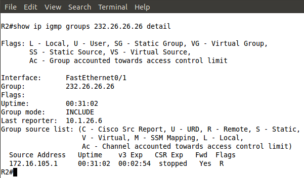
Ping from S3 (RP) to 224.1.1.1 and the mroute table on R3 below:

Pic. 2 - R3 Limits the Traffic.

S4 Configuration:

!
interface Vlan30
 ip address 10.1.30.14 255.255.255.0
 ip igmp join-group 224.10.10.10
!

Ping from S3 to 224.10.10.10. R3 mroute table below:

Pic. 3 - R3 Limits the Traffic.

IP Multicast rate-limit

Lab 164 - IGMP Timers

Prerequisites: CCNP level skills.


Topology

Pic. 1 - Topology Diagram.


Note!
Routers and switches are already configured as per the topology diagram. 

Task 1
On the multicast segment (VLAN 25), there is only one client wishing to receive multicast traffic. Configure R2 and R5 in such a way that they would stop sending multicast traffic immediately upon receiving IGMP Leave message from this client (default 2.5 seconds).

Task 2
Configure the backup querier on VLAN 25 to assume the querier role if it did not hear the query message in 60 seconds (default time is two times the query interval: 120 seconds). Membership query packets should be sent every 15 seconds (default: 60 seconds) by both R2 and R5.


Task 3
R2 and R5 should force their multicast clients to respond to group query with the group report in maximum 5 seconds (default 10 seconds).

Solution


Task 1
On the multicast segment (VLAN 25), there is only one client wishing to receive multicast traffic. Configure R2 and R5 in such a way that they would stop sending multicast traffic immediately upon receiving IGMP Leave message from this client (default 2.5 seconds).

R2 configuration:

!
ip access-list standard ALL_MULTICAST_GROUPS
 permit 224.0.0.0 15.255.255.255
!
interface FastEthernet0/0
 ip address 10.1.25.2 255.255.255.0
 ip pim sparse-mode
 ip igmp immediate-leave group-list ALL_MULTICAST_GROUPS
 speed 100
 full-duplex
!

R5 Configuration:

!
ip access-list standard ALL_MULTICAST_GROUPS
 permit 224.0.0.0 15.255.255.255
!
interface FastEthernet0/0
 ip address 10.1.25.5 255.255.255.0
 ip pim sparse-mode
 ip igmp immediate-leave group-list ALL_MULTICAST_GROUPS
 speed 100
 full-duplex
!


Task 2
Configure the backup querier on VLAN 25 to assume the querier role if it did not hear the query message in 60 seconds (default time is two times the query interval: 120 seconds). Membership query packets should be sent every 15 seconds (default: 60 seconds) by both R2 and R5.


Note!

The querier for multicast is elected based on the lowest IP address on the link (here it has to be R2).


Pic. 2 - DR (designated querier).

R2 configuration:

!
interface FastEthernet0/0
 ip address 10.1.25.2 255.255.255.0
 ip pim sparse-mode
 ip igmp immediate-leave group-list ALL_MULTICAST_GROUPS
 ip igmp query-interval 15
 speed 100
 full-duplex
!

R5 Configuration:

!
interface FastEthernet0/0
 ip address 10.1.25.5 255.255.255.0
 ip pim sparse-mode
 ip igmp query-interval 15
 ip igmp querier-timeout 60
 speed 100
 full-duplex
!


Task 3 
R2 and R5 should force their multicast clients to respond to group query with the group report in maximum 5 seconds (default 10 seconds).

R2 configuration:

!
interface FastEthernet0/0
 ip address 10.1.25.2 255.255.255.0
 ip pim sparse-mode
 ip igmp query-max-response-time 5
 ip igmp immediate-leave group-list ALL_MULTICAST_GROUPS
 ip igmp query-interval 15
 speed 100
 full-duplex
!

R5 Configuration:

!
interface FastEthernet0/0
 ip address 10.1.25.5 255.255.255.0
 ip pim sparse-mode
 ip igmp query-max-response-time 5
 ip igmp query-interval 15
 ip igmp querier-timeout 60
 speed 100
 full-duplex

Lab 163 - IGMP Filtering

Prerequisites: CCNP level skills.


Topology

Pic. 1 - Topology Diagram.


Note!
Routers and switches are already configured as per the topology diagram. 

Task 1
In order to prevent IGMP DoS attacks do not allow R3 to accept more than 10 IGMP states that can be joined to a router from IGMP on its Fa0/0 interface. Also, configure filtering so that R3 allows multicast clients only from the group 224.1.1.0/24.

Solution


Task 1
In order to prevent IGMP DoS attacks do not allow R3 to accept more than 10 IGMP states that can be joined to a router from IGMP on its Fa0/0 interface. Also, configure filtering so that R3 allows multicast clients only from the group 224.1.1.0/24.


R3 Configuration:

!
access-list 1 permit 224.1.1.0 0.0.0.255
!
interface FastEthernet0/0
 ip address 10.1.30.3 255.255.255.0
 ip pim sparse-mode
 ip igmp access-group 1
 ip igmp limit 10
 speed 100
 full-duplex
!

Note!
The 'ip igmp limit' command can be used either globally or on per interface basis.

Verification:
Pic. 2 - R3 Fa0/0 IGMP Limit.

S2 Configuration :

!
interface Vlan30
 ip address 10.1.30.12 255.255.255.0
 ip igmp join-group 224.1.1.1
 ip igmp join-group 224.1.1.2
 ip igmp join-group 224.3.3.3
!

Note!
There are three multicast group joins. The third one is not allowed as per the ACL 1 on R3 (224.3.3.3). It does not get registered.

Pic. 3 - Multicast Groups Registered on R3.

IGMP State Limit

Lab 162 - Anycast RP

Prerequisites: CCNP level skills.


Topology

Pic. 1 - Topology Diagram.


Note!
Routers and switches are already configured as per the topology diagram. All devices use OSPF area 0 as their routing protocol as well as multicast routing. Also, IP PIM Sparse-Mode on VLANs 133 and 143 is enabled.

Task 1
Configure R3 and R4 as RPs for all multicast groups. Ensure that clients choose the closest RP while joining multicast groups (lowest OSPF metric). In case of failure of the closest RP they must be able to use the other one. You are allowed to create extra loopback interface with IP address: 172.16.34.34/32.

Solution

Task 1
Configure R3 and R4 as RPs for all multicast groups. Ensure that clients choose the closest RP while joining multicast groups (lowest OSPF metric). In case of failure of the closest RP they must be able to use the other one. You are allowed to create extra loopback interface with IP address: 172.16.34.34/32.

R3 Configuration:

!
interface Loopback103
 ip address 172.16.103.1 255.255.255.255
 ip ospf 1 area 0
!
interface Loopback34
 ip address 172.16.34.34 255.255.255.255
 ip ospf 1 area 0
!
ip pim rp-address 172.16.34.34
ip msdp peer 172.16.104.1 connect-source Loopback103
ip msdp originator-id Loopback103
!


R4 Configuration:

!
interface Loopback104
 ip address 172.16.104.1 255.255.255.255
 ip ospf 1 area 0
!
interface Loopback34
 ip address 172.16.34.34 255.255.255.255
 ip ospf 1 area 0
!
ip pim rp-address 172.16.34.34
ip msdp peer 172.16.103.1 connect-source Loopback104
ip msdp originator-id Loopback104
!

S3 Configuration:

!
ip pim rp-address 172.16.34.34
!

Verification:
Pic. 2 - MSDP Peer Session.

Lab 161 - Source Specific Multicast

Prerequisites: CCNP level skills.


Topology

Pic. 1 - Topology Diagram.


Note!
Routers and switches are already configured as per the topology diagram. All devices use OSPF area 0 as their routing protocol as well as multicast routing.

Task 1
Enable PIM Sparse Mode between R2 and R5 on FastEthernet link.

Task 2
Make sure that users on VLAN 26 can receive multicast traffic sent to 232.26.26.26 only from the source of 172.16.105.5 (R5 Loopback105). Verify your solution.

Solution


Task 1
Enable PIM Sparse Mode between R2 and R5 on FastEthernet link.

R2 Configuration:

!
interface FastEthernet0/0
 ip address 10.1.25.2 255.255.255.0
 ip pim sparse-mode
 speed 100
 full-duplex
!
interface FastEthernet0/1
 ip address 10.1.26.2 255.255.255.0
 ip pim sparse-mode
 ip igmp version 3
 speed 100
 full-duplex
!

Note!
Since the Task 2 stipulates that Source Specific Multicast must be used, IGMP v3 hast to be configured on F0/1 interface.

R5 Configuration:

!
interface Loopback105
 ip address 172.16.105.1 255.255.255.128
 ip pim sparse-mode
!
interface FastEthernet0/0
 ip address 10.1.25.5 255.255.255.0
 ip pim sparse-mode
 speed 100
 full-duplex
!

Task 2
Ensure that users on VLAN 26 can receive multicast traffic sent to 232.26.26.26 only from the source of 172.16.105.5 (R5 Loopback105). Verify your solution.

R2 and R5 Configuration:

!
ip pim ssm default
!

R6 Configuration:

!
interface FastEthernet0/0
 ip address 10.1.26.6 255.255.255.0
 ip igmp join-group 232.26.26.26 source 172.16.105.1
 ip igmp version 3
 speed 100
 full-duplex
!

Verification:
Pic. 2 - Mroute Entry on R2.

Pic. 3 - R2 and R3 Mroute Table.

Pic. 4 - Ping Test.

Note!
Apart from a classic multicast (Any Source Multicast), the Source Specific Multicast method allows clients to choose the source of multicast feed. It requires IGMP version 3 though. SSM builds SPT tree and does not require RP to operate. The command 'ip pim ssm' with the keyword 'default' uses the range 232.0.0.0/8 addresses. The syntax is as follows:

Pic. 5 - IP PIM SSM Command.


Monday, November 14, 2011

Lab 160 - Multicast Stub Routing

Prerequisites: CCNP level skills.

Personal Note!
Other dimensions and universes which existence we sense, took a more tangible form a few days ago. My friend, artist, who goes by the name Valcari, seems to live in many of them at the same time. He is no longer the same person I have known for ages. Not better, not worse ... just different. Evolution?

Topology

Pic. 1 - Topology Diagram.


Note!
Routers and switches are already configured as per the topology diagram. All devices use OSPF area 0 as their routing protocol as well as multicast routing.


Task 1
R1 is to be the RP for all multicast groups. VLAN 26 clients will join the group 224.26.26.26. R4 is going to be server for the group 224.26.26.26.

Task 2
Configure R1 and R2 in such a way that they do not form PIM adjacency over Frame-Relay cloud, but IGMP join messages must be sent to R1 and the multicast traffic from from VLAN 14 should be sent via WAN connection to the clients in VLAN 26.

Solution


Task 1
R1 is to be the RP for all multicast groups. VLAN 26 clients will join the group 224.26.26.26. R4 is going to be server for the group 224.26.26.26.

R1 Configuration:

!
interface Loopback101
 ip address 172.16.101.1 255.255.255.255
 ip pim sparse-mode
!
interface FastEthernet0/0
 ip address 10.1.14.1 255.255.255.0
 ip pim sparse-mode
 speed 100
 full-duplex
!
interface Serial0/0.125 multipoint
 ip address 10.1.125.1 255.255.255.0
 ip pim dense-mode
 ip ospf network point-to-multipoint
 snmp trap link-status
 frame-relay map ip 10.1.125.1 102
 frame-relay map ip 10.1.125.5 105 broadcast
 frame-relay map ip 10.1.125.2 102 broadcast
!
ip pim rp-address 172.16.101.1
!


R4 Configuration:
!
interface FastEthernet0/0
 ip address 10.1.14.4 255.255.255.0
 ip pim sparse-mode
 speed 100
 full-duplex
!
ip pim rp-address 172.16.101.1
!

Note!
At this stage R1 configuration is not complete yet. I use 'dense-mode' on Serial0/0.125 interface, otherwise the multicast traffic would not be sent down to R2. In the next task, I will allow R2 to send the IGMP join-message to be sent towards R1.


Task 2

Configure R1 and R2 in such a way that they do not form PIM adjacency over Frame-Relay cloud, but IGMP join messages must be sent to R1 and the multicast traffic from from VLAN 14 should be sent via WAN connection to the clients in VLAN 26.

R1 Configuration:
!
access-list 1 deny   10.1.125.2
access-list 1 permit any
!
interface Serial0/0.125 multipoint
 ip address 10.1.125.1 255.255.255.0
 ip pim neighbor-filter 1
 ip pim dense-mode
 ip ospf network point-to-multipoint
 snmp trap link-status
 frame-relay map ip 10.1.125.1 102
 frame-relay map ip 10.1.125.5 105 broadcast
 frame-relay map ip 10.1.125.2 102 broadcast
!

Note!
The ACL will make it impossible for R2 to form PIM adjacency over FR link.

R2 Configuration:
!
interface FastEthernet0/1
 ip address 10.1.26.2 255.255.255.0
 ip pim dense-mode
 ip igmp helper-address 10.1.125.1
 ip igmp join-group 224.26.26.26
 speed 100
 full-duplex
!
interface Serial0/0
 ip address 10.1.125.2 255.255.255.0
 ip pim dense-mode
 encapsulation frame-relay
 ip ospf network point-to-multipoint
 clock rate 2000000
 frame-relay map ip 10.1.125.5 201
 frame-relay map ip 10.1.125.1 201 broadcast
 frame-relay map ip 10.1.125.2 201
 no frame-relay inverse-arp
!

Note!
IP igmp helper address is going to forward IGMP join messages received on VLAN 26 interface up to R1.

Verification:
Pic. 2 - PIM Enabled Interface on R2.

Pic. 3 - R2 Recognizes R1 as PIM Neighbor.

Pic. 4 - R1 Does Not Create Adjacency with R2.

Pic. 5 - R1 Receives IGMP Join Message
Forwarded by R2.

Pic. 6 - Multicast Traffic.

Saturday, November 12, 2011

Lab 159 - BSR Propagation Filtering

Prerequisites: CCNP level skills.


Topology

Pic. 1 - Topology Diagram.


Note!
Routers and switches are already configured as per the topology diagram. All devices use OSPF area 0 as their routing protocol as well as multicast routing.


IP PIM Sparse Mode has been enabled on VLANs: 14, 30, 133, 143.

Task 1
Configure R1 as the RP and BSR candidate for all multicast groups. Use the most stable interface to accomplish the task.

Task 2
Ensure that R3 does not receive information about RP.

Solution


Task 1
Configure R1 as the RP and BSR candidate for all multicast groups. Use the most stable interface to accomplish the task.


R1 Configuration:

!
interface Loopback101
 ip address 172.16.101.1 255.255.255.255
 ip pim sparse-mode
!
ip pim bsr-candidate Loopback101 0
ip pim rp-candidate Loopback101
!


Verification:
Pic. 2 - RP Information on R3.


Note!
Without filtering, R3 receives information about RP.


Task 2
Ensure that R3 does not receive information about RP.
S3 Configuration:
!
interface Vlan133
 ip address 10.1.133.10 255.255.255.0
 ip pim bsr-border
 ip pim sparse-mode
!

Verification:
Pic. 3 - RP information on R3.


The previous information about RP slowly expires. R3 loses information about RP.

Thursday, November 10, 2011

Lab 158 - BSR with Multiple RPs

Prerequisites: CCNP level skills.

Personal Note!
1:23  in the morning. Full moon makes the mind wander ...

Ying and Yang, day and night, one and zero ... so much of this dichotomy.
Perhaps if you were good in the first half of your life, in the second you should ... find something interesting ... (LOL).


Topology

Pic. 1 - Topology Diagram.


Note!
Routers and switches are already configured as per the topology diagram. All devices use OSPF area 0 as their routing protocol as well as multicast routing.

Task 1
Enable PIM Sparse mode on VLANs: 14, 30, 133, 144. Do not enable PIM protocol on VLAN interfaces of S2 and S4.

Task 2
Configure R1 and R4 as RP candidates for all multicast groups. S3 should disseminate RP-set information. Configure hash-mask-length so that the load on RPs is evenly distributed with groups of four multicast addresses as shown below:
  • Group 1: 224.1.1.0, 224.1.1.1, 224.1.1.2, 224.1.1.3 given to one RP.
  • Group 2: 224.1.1.4, 224.1.1.5, 224.1.1.6, 224.1.1.7 given to another RP.
  • Group 3: 224.1.1.8, 224.1.1.9, 224.1.1.10, 224.1.1.11 given to the first RP.
  • etc.
Solution

Task 1
Enable PIM Sparse mode on VLANs: 14, 30, 133, 144. Do not enable PIM protocol on VLAN interfaces of S2 and S4.

R1 Configuration:
!
interface FastEthernet0/0
 ip address 10.1.14.1 255.255.255.0
 ip pim sparse-mode
 speed 100
 full-duplex
!

R3 Configuraiton:
!
interface FastEthernet0/0
 ip address 10.1.30.3 255.255.255.0
 ip pim sparse-mode
 speed 100
 full-duplex
!
interface FastEthernet0/1
 ip address 10.1.133.3 255.255.255.0
 ip pim sparse-mode
 speed 100
 full-duplex
!

R4 Configuration:
!
interface FastEthernet0/0
 ip address 10.1.14.4 255.255.255.0
 ip pim sparse-mode
 speed 100
 full-duplex
!
interface FastEthernet0/1
 ip address 10.1.143.4 255.255.255.0
 ip pim sparse-mode
 speed 100
 full-duplex
!

S3 Configuration:
!
interface Vlan133
 ip address 10.1.133.10 255.255.255.0
 ip pim sparse-mode
!
interface Vlan143
 ip address 10.1.143.10 255.255.255.0
 ip pim sparse-mode
!

Task 2
Configure R1 and R4 as RP candidates for all multicast groups. S3 should disseminate RP-set information. Configure hash-mask-length so that the load on RPs is evenly distributed with groups of four multicast addresses as shown below:
  • Group 1: 224.1.1.0, 224.1.1.1, 224.1.1.2, 224.1.1.3 given to one RP.
  • Group 2: 224.1.1.4, 224.1.1.5, 224.1.1.6, 224.1.1.7 given to another RP.
  • Group 3: 224.1.1.8 224.1.1.9, 224.1.1.10, 224.1.1.11 given to the first RP.
  • etc.
S3 Configuration:
!
interface Loopback107
 ip address 172.16.107.1 255.255.255.255
 ip pim sparse-mode 
!
ip pim bsr-candidate Loopback107 30

!
R1 Configuration:
!
interface Loopback101
 ip address 172.16.101.1 255.255.255.255
 ip pim sparse-mode
!
ip pim rp-candidate Loopback101
!

R4 Configuration:
!
interface Loopback104
 ip address 172.16.104.1 255.255.255.255
 ip pim sparse-mode
!
ip pim rp-candidate Loopback104
!

Verification:

S2 Configuration:
!
interface Vlan30
 ip address 10.1.30.12 255.255.255.0
 ip igmp join-group 224.1.1.0
 ip igmp join-group 224.1.1.1
 ip igmp join-group 224.1.1.2
 ip igmp join-group 224.1.1.3
!

S4 Configuration:
!
interface Vlan30
 ip address 10.1.30.14 255.255.255.0
 ip igmp join-group 224.1.1.4
 ip igmp join-group 224.1.1.5
 ip igmp join-group 224.1.1.6
 ip igmp join-group 224.1.1.7
!

Pic. 2 - RP (R1) Mapping.
Pic. 3 - RP (R4) Mapping.

Note!
The highest hash value denotes the RP for the group.

R1 (172.16.101.1) is the RP for groups:
  • 224.1.1.0
  • 224.1.1.1
  • 224.1.1.2
  • 224.1.1.3
 R4 is RP for the groups:
  • 224.1.1.4
  • 224.1.1.5
  • 224.1.1.6
  • 224.1.1.7

Wednesday, November 9, 2011

Lab 157 - PIM Bootstrap Router

Prerequisites: CCNP level skills.

Personal Note!
Finding things out is a real pleasure ... Time to continue to get the buzz before all these memories drown in oblivion ...

Topology

Pic. 1 - Topology Diagram.


Note!
Routers and switches are already configured as per the topology diagram. All devices use OSPF area 0 as their routing protocol.

Task 1
Enable PIM Sparse mode on the following interfaces:
  • R1 - Fa0/0
  • R1 - S0/0.125
  • R2 - Fa0/0
  • R2 - Fa0/1
  • R2 - S0/0
  • R4 - Fa0/0
  • R5 - Fa0/0
  • R5 - S0/0
Task 2
Configure R2 to be BSR and R5 to be RP. Use the most stable interface on R2 and R5 to accomplish the task.


Task 3
Use R4 to simulate multicast server sending packets to 224.46.46.46. Users on VLAN 26 should receive this multicast feed. Verify your solution.


Solution

Task 1
Enable PIM Sparse mode on the following interfaces:
  • R1 - Fa0/0
  • R1 - S0/0.125
  • R2 - Fa0/0
  • R2 - Fa0/1
  • R2 - S0/0
  • R4 - Fa0/0
  • R5 - Fa0/0
  • R5 - S0/0

R1 Configuration:
!
ip multicast-routing
!
interface FastEthernet0/0
 ip address 10.1.14.1 255.255.255.0
 ip pim sparse-mode
 speed 100
 full-duplex
!
interface Serial0/0.125 multipoint
 ip address 10.1.125.1 255.255.255.0
 ip pim sparse-mode
 ip ospf network point-to-multipoint
 snmp trap link-status
 frame-relay map ip 10.1.125.2 102 broadcast
 frame-relay map ip 10.1.125.5 105 broadcast
 frame-relay map ip 10.1.125.1 102
!

R2 Configuration:
!
ip multicast-routing
!
interface FastEthernet0/0
 ip address 10.1.25.2 255.255.255.0
 ip pim sparse-mode
 speed 100
 full-duplex
!
interface FastEthernet0/1
 ip address 10.1.26.2 255.255.255.0
 ip pim sparse-mode
 speed 100
 full-duplex
!
interface Serial0/0
 ip address 10.1.125.2 255.255.255.0
 ip pim sparse-mode
 encapsulation frame-relay
 ip ospf network point-to-multipoint
 clock rate 2000000
 frame-relay map ip 10.1.125.2 201
 frame-relay map ip 10.1.125.1 201 broadcast
 frame-relay map ip 10.1.125.5 201
 no frame-relay inverse-arp
!

R4 Configuration:
!
ip multicast-routing
!
interface FastEthernet0/0
 ip address 10.1.14.4 255.255.255.0
 ip pim sparse-mode
 speed 100
 full-duplex
!

R5 Configuration:
!
ip multicast-routing
!
interface FastEthernet0/0
 ip address 10.1.25.5 255.255.255.0
 ip pim sparse-mode
 speed 100
 full-duplex
!
interface Serial0/0
 ip address 10.1.125.5 255.255.255.0
 ip pim sparse-mode
 encapsulation frame-relay
 ip ospf network point-to-multipoint
 clock rate 2000000
 frame-relay map ip 10.1.125.1 501 broadcast
 frame-relay map ip 10.1.125.2 501
 frame-relay map ip 10.1.125.5 501
!


Verification:
Pic.2 - PIM Neighbors of R1.

Pic. 3 - PIM Neighbors of R2.


Task 2
Configure R2 to be BSR and R5 to be RP. Use the most stable interface on R2 and R5 to accomplish the task.

R2 Configuration:
!
interface Loopback102
 ip address 172.16.102.1 255.255.255.255
 ip pim sparse-mode
!
ip pim bsr-candidate Loopback102 0
!

R5 Configuration:
!
interface Loopback105
 ip address 172.16.105.1 255.255.255.128
 ip pim sparse-mode
!
ip pim rp-candidate Loopback105
!

Verification:
Pic. 4 - RP Information on R4.

Pic. 5 - RP Information on R5.


Note!
The RP candidate uses default priority 0 (Cisco implementation, whereas the standard uses 192, max. 255). RP with the LOWEST priority (0) is preferred.
http://www.cisco.com/en/US/docs/ios/ipmulti/command/reference/imc_04.html#wp1055223

In PIMv2, a BSR is the equivalent of Mapping Agent used in Auto-RP. BSR default priority is 0 (0-255). Candidate with the HIGHEST priority is preferred if multiple BSR candidates exist.

BSR does NOT elect the best RP. The group range to RP mapping is only distributed distributed to routers and they choose the best one for a group.
This information is disseminated on a hop-by-hop basis.


Task 3

Use R4 to simulate multicast server sending packets to 224.46.46.46. Users on VLAN 26 should receive this multicast feed. Verify your solution.

R6 Configuration:

!
interface FastEthernet0/0
 ip address 10.1.26.6 255.255.255.0
 ip igmp join-group 224.46.46.46
 speed 100
 full-duplex
!

Verification:
Pic. 6 - Mroute Table on R2.

Pic. 7 - Mroute Table on R5.

Note!
R5 is the RP for all multicast groups. In the output the RPF nbr 0.0.0.0 implies this fact. The (*,G) entries show up in the client-to-RP path as expected).

Pic. 8 - Ping (server feed) from R4 results.